LOADING CAD MODEL
Field-tested small-scale prototype

Full awareness.
Active intervention.

EMBER connects satellite observation, drone verification and early warning to a precision ground launch system, so the first response to a new fire starts in minutes, from a safe distance.

01 / Software . EMBER Watch

EMBER Watch.
Find it. Confirm it. Hand it off.

The sensing layers run on one operator console. Satellite hotspots, watch zones, drone fire identification and the launch handoff share the same map, so a detection becomes a firing solution without anyone retyping coordinates. Try the visual modes or go full screen.

EMBERWATCH
VISUAL MODE
LIVE
SIMULATED

Interface concept with simulated data. NASA FIRMS data courtesy of NASA EOSDIS.

02 / The launcher . what we already built

A working small-scale prototype.
Take it apart.

This is the 3D model of our small-scale prototype, loaded in your browser. Select a subsystem to isolate it. It proves the architecture (sensing, aiming, pneumatic launch and safety checks) that the full-scale, vehicle-mounted platforms will scale up.

DRAG TO ORBIT . SCROLL OR PINCH TO ZOOM
Subsystems
Elevation12.3 degrees of travel

Electric motor and gearbox on a 300 mm lead screw, with a 3D printed piston guided by grooves in the motor housing.

Lateral12.3 degrees of traverse

Electric motor on a 300 mm lead screw. A repurposed caster wheel swivel prevents overconstraint.

PneumaticsQuick exhaust valve release

A 1 inch quick exhaust valve dumps the 128 PSI-rated reservoir into the 3 ft barrel, backed by a 125 psi spring release, a relief solenoid and a compressor over-pressure breaker.
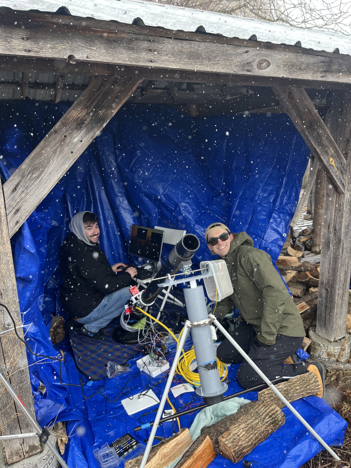
Two EMBER team members operating the launcher from a tarp shelter during the winter field test
Winter field testShots fired in snow from a tarp shelter, laden 1 kg shells, live GPS targeting.
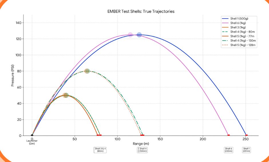
Chart of measured shell trajectories out to 250 metres
Measured trajectoriesShells landed between 80 m and 250 m.
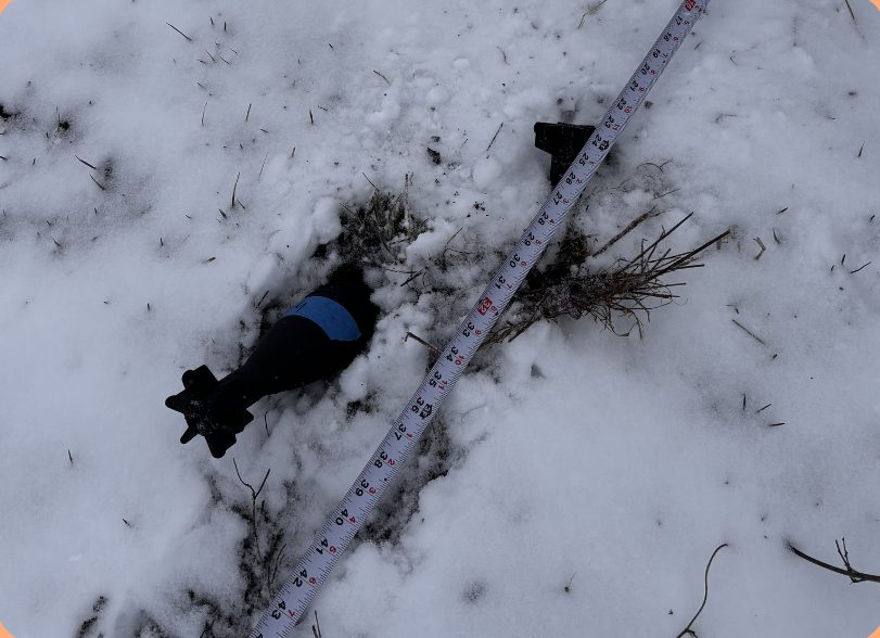
A recovered shell in the snow beside a measuring tape
Shell recovered intactBiodegradable printed shell. Integrity held at launch and impact.
230 mMax range carrying a 1 kg payload (250 m unladen)
0.94 mAverage shell-to-shell distance at 130 m
0.96 mAverage shell-to-shell distance at 80 m
62.9%Purchased parts. 20% 3D printed, 17.1% recycled
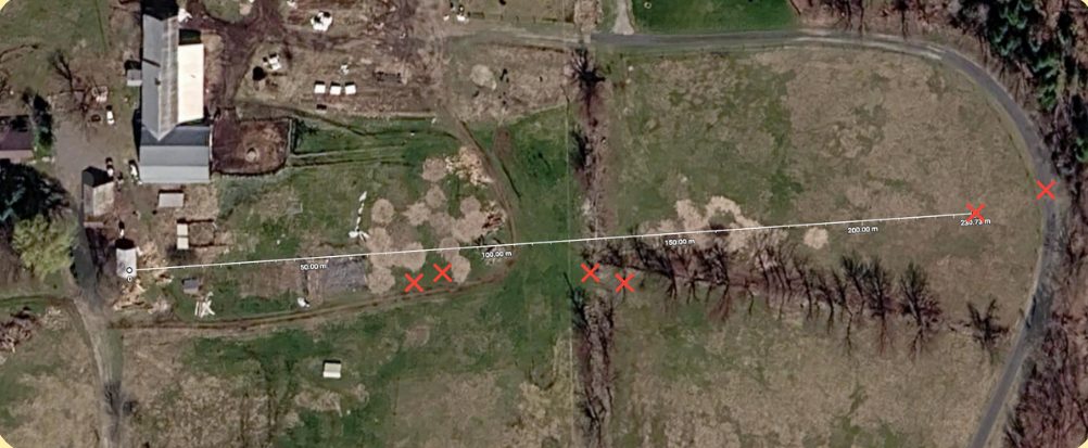
Aerial map of the test field with shell impact markers
Impact mapLanding points plotted along the firing line on the test field.
PRODUCT DEMO VIDEO
Electronics

Distributed power and control

  • Custom power distribution board
  • Onboard computer reading pressure and position sensors
  • Motor controllers for aiming
  • Switched safety and firing actuators
Software

Web-based command

  • Web-based operator dashboard
  • Live sensor streaming
  • Map-based targeting and ballistics
  • Emergency stop at all times
03 / The payload

Maximizing
target impact.

The tested shells carried inert 1 kg loads. The next shell is built to make every kilogram count: a self-foaming design that keeps two reactants apart in flight, mixes them on impact and expands about a liter of solution into roughly 14 liters of clinging foam exactly where it lands.

ACTIVE EXTINGUISHING

Fired directly onto a spot fire or new ignition, the foam smothers the flame, cools the fuel and cuts off oxygen, knocking it down before it can spread.

PREVENTION . FIREBREAK

Fired ahead of the fire onto dry grass and brush, the foam coats unburned fuel and holds moisture against it, building a wetted barrier the flame front struggles to cross.

CHAMBER A

710.5 g water with class A foam concentrate and 53.3 g sodium bicarbonate.

CHAMBER B

36.2 g aluminum sulfate, sealed behind a frangible barrier that shatters on impact.

REACTION

The two charges are stoichiometrically matched, releasing about 0.63 mol of CO2, roughly 14 to 15 liters of gas to drive the foam out.

PRINTED

Every EMBER shell is 3D printed in biodegradable material, so casing fragments left after a burst break down in the field instead of littering it.

CASING

200 g biodegradable printed bursting casing with V-notch score lines tuned to rupture near a 100 psi internal spike, weighted nose and rear stabilizer fins.

WHY FOAM

Class A foam concentrate lowers the surface tension of water so it soaks into dry fuel instead of beading and running off, and the foam blanket insulates the fuel from radiant heat.

DRAG TO ROTATE . ALL PARTS 3D PRINTED IN BIODEGRADABLE MATERIAL
EMBER / PAYLOAD / FS-1 SELF-FOAMING SUPPRESSION SHELL . SECTION A-A L . SIZED TO BORE Ø BORESLIP FIT 123456789 PARTS LIST 1Weighted nose cone 2Inertial striker (opt.) 3Forward bulkhead 4Casing, biodeg. print200 g 5V-notch score lines 6Chamber A763.8 g water + class A foamconcentrate 710.5 gNaHCO3 dissolved 53.3 g 7Frangible barrier 8Chamber B36.2 g Al2(SO4)3, isolated 9Stabilizer fins, base TOTAL1000.0 g MASS BUDGET . 1.000 kg CASING 20%WATER + FOAM CONCENTRATE 71.05%NaHCO3 5.33%Al2(SO4)3 3.62% DETAIL B . SCORE LINE 60° VRuptures near a 100 psiinternal spike, not in flight. FUNCTION SEQUENCE 1 . FLIGHT Reactants sealed apart.Inert until impact. 2 . IMPACT Barrier shatters, strikerdrives B into A. 3 . REACTION Al2(SO4)3 + 6 NaHCO3→ 2 Al(OH)3 + 3 Na2SO4 + 6 CO2 0.106 mol + 0.634 mol . matched0.63 mol CO2 . about 14 to 15 L gasAl(OH)3 gel helps stabilize the foam. 4 . BURST Casing opens on scorelines, foam expelled. EMBER . FS-1 SHELL CONCEPT . NOT VALIDATED SCALE NTSREV B MASS 1.000 kgSHEET 1/1 PRINT . BIODEG.2026-10-31
FS-1 self-foaming shell, concept drawing. All shell parts are 3D printed in biodegradable material. Masses from the team's design; dimensions set by the final barrel bore. Not yet lab validated.
04 / Full system integration

One pipeline.
From orbit to impact.

Wildfires are cheapest to stop in their first minutes, and hardest to reach. EMBER is designed as four connected layers: wide-area observation, close-range verification, operator alerting and a ground launch platform that can act on a confirmed GPS target. Step through the sequence below.

EMBER / RESPONSE SIMULATIONILLUSTRATIVE CONCEPT
01 / OBSERVE

Spot the heat signature

A satellite pass detects a thermal anomaly in remote terrain and assigns it coarse coordinates.

Auto-plays. Click a stage to jump, drag the scene to look around.
01 / OBSERVE

Satellite watch

Ingest thermal hotspot data from orbit to cover areas no lookout or patrol can watch continuously.

  • Wide-area thermal anomaly detection
  • Coarse geolocation of new hotspots
  • Public hotspot feeds first, dedicated sensing later
02 / VERIFY

Drone confirmation

A drone launched to the reported coordinates confirms the fire, filters false positives and refines the target position.

  • Thermal and visual camera
  • Refined GPS fix and fire perimeter
  • Live wind and terrain context
03 / ALERT

Early warning

Verified detections become a prioritized alert for qualified operators, with location, size, wind and a suggested firing solution.

  • Sensor fusion and confidence scoring
  • Operator dashboard and notifications
  • A person authorizes every action
04 / RESPOND

Integrated launch

A vehicle-mounted launch platform receives the target, solves the ballistics, self-checks pressure and aims the barrel for operator-approved release.

  • GPS targeting and auto-aim (built)
  • Pressure integrity checks (built)
  • Interchangeable suppression modules
05 / The mobile platform

One vehicle.
Swappable missions.

The next platform moves EMBER onto a vehicle that already carries a compressor and generator, like a fire apparatus does. The launch bay accepts modules sized to the job: precise shots on spot fires, or a single action that lays a firebreak across the fire's path.

MODULE A . DIRECT ATTACK

Multi-tube foam launcher

A rack of barrels scaled from the prototype, fed by the vehicle's air supply. Each tube carries a foaming shell aimed at a verified GPS target for spot fires and new ignitions.

MODULE A . MULTI-TUBE FOAM LAUNCHER CONCEPT . NTS 12345678 1 6-tube pod2 Elevation drive3 Turntable4 Compressor, tanks5 Generator6 Operator station7 Stabilizer jacks8 Air manifold, QEVs Each tube fires one foaming shell at a verified GPS target.
Precision firstBuilds directly on the tested aiming, ballistics and pressure-check software.
Many targets, one stopIndependent tubes let one vehicle answer several spot fires from a single safe position.
Trade-offEvery shot draws on the vehicle's compressed air supply, which limits sustained volume.
Extends tested hardware
MODULE B . FUTURE ROADMAP PRODUCT

500 ft linear suppression line

To build a firebreak in a single action, this module swaps the tubes for a 500 ft flexible line. The scaled-up EMBER launcher fires a pilot projectile that tows the line across the fire's path. No explosives are involved: the line is a woven, scored sleeve packed with dry retardant such as monoammonium phosphate around a central air channel, fed through the tether from the vehicle's compressor.

MODULE B . LINE LAUNCH VEHICLE CONCEPT . NTS 12345678 1 Scaled launcher2 Turntable3 Line canister4 Pilot projectile5 Compressor, air feed6 Generator7 Operator station8 Stabilizer jacks The prototype launcher, scaled up, tows the line out from its canister.
1. PressurizeOnce the line is down and the area is clear, the vehicle's compressor pressurizes the central air channel through the tether.
2. Disperse retardantThe sleeve splits along its scored seams and blows dry retardant out over a band along the full 500 ft, coating vegetation on the defended side.
3. Hold and anchorTreated fuel resists ignition and catches wind-blown embers. The laid line marks a ready-made control line that crews can widen with hand tools.
DESIGN NOTENo explosives. The line is deployed by the same pneumatic launch principle as the prototype and activated with compressed air. Dispersal coverage will be validated through modelling and inert deployment trials.
Future roadmap concept
06 / Future product . Module B

500 feet of firebreak.
One action.

Our roadmap product: the same EMBER launcher, scaled up and mounted on a vehicle, firing a pilot projectile that lays a 500 ft suppression line in one shot. The animation runs the line as a simulated rope, so it falls and drapes the way a real line would. Pick a chapter or let it run.

EMBER / MODULE B / CONCEPT ANIMATION00:00
01 / ARRIVE

Stage ahead of the front

Concept visualization. Line length 152 m (500 ft). Retardant band width illustrative. Launcher shown is the full prototype CAD, scaled up and vehicle mounted.

EMBER / MODULE B / LAUNCH VEHICLE THE EMBER LAUNCHER, SCALED UP AND VEHICLE MOUNTED . SIDE ELEVATION 123456789 KEY 1Scaled EMBER launcher: barrel, QEV, reservoir 2Elevation drive, lead screw 3Lateral turntable 4Pilot projectile, tows the line 5Line canister, 500 ft flaked 6Compressor and air reservoirs 7Generator, 24 V and 12 V bus 8Operator station, EMBER controller 9Stabilizer jacks Same sense, aim, pressure-check, authorize loop. FUTURE ROADMAP PRODUCT . CONCEPT . NOT TO SCALE
EMBER / MODULE B / SUPPRESSION LINE 500 FT RETARDANT LINE . HOW IT DISPERSES FUTURE ROADMAP PRODUCT . CONCEPT . NO EXPLOSIVES . PNEUMATIC DISPERSAL 1 . SECTION A-A . AS LAID Scored seams, open at set pressureWoven hi-vis jacket, porousDry retardant powder (MAP)Inner pressure sleeveCentral air channel 2 . SECTION A-A . PRESSURIZED GROUND Compressed air from thevehicle fills the channel. The sleeve inflates, seamssplit along their length. Powder is blown up and out,biased by the scoring towardthe defended side. 3 . SIDE ELEVATION . ACTIVATION RUNS FROM THE TETHER OUTWARD VEHICLE AIR FEED PRESSURE FRONT TRAVELS DOWN THE LINE not yet pressurized 152 m . 500 ft 4 . PLAN VIEW . AFTER DISPERSAL FIRE SIDE . FLAME FRONT ADVANCING LAID LINE RETARDANT BAND . TREATED FUEL DEFENDED SIDE . CREWS ANCHOR HERE band THE RETARDANT Monoammonium phosphate (MAP), dry powder The same phosphate salt used in long-term wildlandretardants and ABC dry-chemical extinguishers. How it works When heated, it changes how the fuelbreaks down: the grass chars instead of releasingflammable gas, so flames and embers struggle to catch. Why dry No water to carry, so the line stays lightenough to be towed out by the pilot projectile. Coverage and band width to be validated in inert trials. 1 Lay 2 Pressurize through the tether 3 Seams split, powder disperses 4 Treated band holds the front